


SSDとストレージインテリジェンス(Storage Intelligence)仕様
SDC(Storage Developer Conference)の取材記事として、Storage Intelligenceの話題が出ていました。日本語記事は初めて見ました。英語記事でもこの話題はかなり少ないと思いますが。
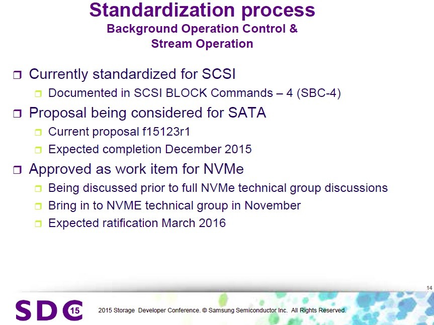
具体的には4つの技術をSSDおよびストレージシステムに導入することを説明した。(1)SSDのバックグラウンド動作をホストが制御する機能、(2)SSDに書き込むデータのストリーム化、(3)ストレージのオブジェクト化、(4)ストレージ内部でのコンピューティング、である。
記事にあるようにSamsungが発表していたようですが、SSDベンダー各社取り組みあり、SAS, SATA, PCIe(NVMe)それぞれで標準化が進んでいます(記事でも下記スライド紹介されています)。SCSI(SAS)では標準化済み、SATAでは今年12月までに標準化予定、PCIe(NVMe)では現在議論中で来年以降標準化の動き、とありますね。
ご存知の方も多いと思いますが、SSDの記憶媒体であるNANDフラッシュメモリの特徴として、
- 1)データ書き込みがページサイズという大きな単位(※SCSI I/Oの単位であるセクタサイズ(通常512byte)よりも大きなサイズ)
- 2)データの上書きが仕組み上できないので、上書きする場合は一度消してから新しく書く(※データ消去はページサイズよりも大きなブロックサイズ)
という点があります。上書きができないというのはHDDとは大きく異なる点で、そんなことをホストアプリケーションやOSから意識する必要がないよう、SSD内部で仮想的に上書きできるようになっています。
最近の(少なくとも一定以上のランクの)SSDではデータ管理を仮想化しているため、物理アドレスと論理アドレスはマップ管理されており、大きなサイズでデータ上書きする場合は、新しいブロックに新しいデータを書いて、古いデータを無効化するだけなので簡単(余分な内部ライトは発生しない)ですが、細かい単位でデータを上書きする場合は、古いブロックの上書きされていないデータを新しいブロックにコピーする必要があり、この時に余分な内部ライト(古いブロックから新しいブロックへのコピーライト)が発生するため、ライトの増幅ということでWrite Amplificationと呼んでいます。ライトの増幅比率をWrite Amplification Factor(WAF「わふ」)と言っています。SSDの書き込み回数はNANDの仕様で決まっていますので、SSDの耐久性を向上させるというのは、いかにWAFを小さくするかというシンプルな話になります。
(余談ですが、SSDはOP(「おーぴー」)(Over Provisioning)という余剰容量を内部的に持っていて、OP比率でWAFは大きく変わります。OPを横軸、WAFを縦軸のグラフにすると、グラフの形は結構ダイナミックに右に上がっていくイメージです。。OPが大きいSSDは耐久性及び書き込み性能が相対的に高く、OPが小さいSSDは耐久性及び書き込み性能が相対的に低いです。OPと書き込み性能が連動するのは、OPが大きいと書き込みに伴う内部処理のワーキングエリアが大きいので、色々制御を工夫する余地が広がるためです。SSDのコストはNAND価格の割合が高いので、OPを大きくするとその分SSDが高価になります。また、SSDの性能と消費電力も相関関係があり、消費電力が大きくてOPも大きくてよければ性能はかなり上げられます。消費電力は仕様上レギュレーションがありますし、コストも抑える必要があるので、制約の中でいかにチューニングするかというF1みたいな地味な話になります。今回は出ませんがDWPDと合わせて、OP,WAF,DWPDくらいが説明できればSSDにかなり詳しい人かと思います。)
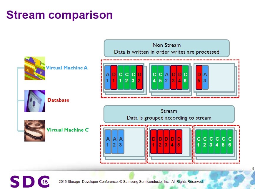
Storage Intelligence仕様でのStreamは、WAFを低減させるために、ホスト(アプリ)からのI/Oストリームに番号を付けて、例えば、「もしアプリが上書きしないアプリなら、データをそっとしておく」ということを実現することができます。ブロック内に上書きしないアプリ(A)(メディアファイル等)が書いたデータと、上書きしまくるアプリ(B)(データベース等)が書いたデータが混じってしまうと、(B)の上書きの影響で、(A)のデータも将来的にブロックを引っ越しする必要が発生し、WAF的にうれしくない状況になるので、(A)と(B)のブロックを分けるようなことを実現できます。(何を言っているのか分かりますでしょうか。。世の中に100万円単位でしか出金できない銀行口座しかない場合、生活費と長期預金の銀行口座は分けておいた方が銀行に行く回数が減らせて効率的というようなことです。あ、でもお金には色が付いてないのでデータとは違いますね、、下のスライドでは赤いのを隔離しておこうということです。)
もう一つの(簡単な方の)仕様のBackground operationは、SSDの内部処理は色々あって、ホストのアクセス性能に影響を与える可能性がある(発表資料では実際に影響が出ているようです)ということで、ホストアクセスが少ないタイミングをホストからSSDに教えるという仕様です。
SSDの作りは各社、各モデル色々あると思いますので、Storage Intelligenceの効果は各SSDに依存することになりますが、ホストからの設定等を行うコマンド仕様を取り決めしているという状況です。
SAS(SCSI)では、SBC-4 (SCSI Block Commands)の中でStorage Intelligence仕様が書かれています。
SCSI Block Commands - 4 (SBC-4)
続きを読む
HDDのファームウェアにスパイウェアを仕込む話
下記日本語記事は、かなり記事のトーンがオリジナルと異なります。
HDDのファームウェアに感染するマルウェアが登場、逃れる術はないことが判明 - GIGAZINE
下記が英語元記事(ロイター)。通常のマルウェアのように感染する話とは全く異なります。HDDが感染する訳ではなく、HDDのファームウェアを書き換えることができた場合には、攻撃者は脆弱性を作り出したり、攻撃をしやすくなる、という話。
Russian researchers expose breakthrough U.S. spying program | Reuters
Raiu said the authors of the spying programs must have had access to the proprietary source code that directs the actions of the hard drives.
ライウ氏(カスペルスキー社の研究者)によると、スパイプログラムの作者は、(各HDDベンダが開発する)独自のソースコードを入手し(ソースコード改造後にHDDのファームウェアを書き換えて)、HDDの動作を制御する必要がある。
"There is zero chance that someone could rewrite the [hard drive] operating system using public information," Raiu said.
「何者かが公開された情報を用いてHDDのオペレーティングシステム(ファームウェア)を書き換えられる可能性はゼロである」とライウ氏は述べた。
eSSD (enterprise SSD)
エンタープライズ用途(個人使用のPCではなく、データセンターや企業システム、インフラシステムで使うIT機器)で使うことのできる特性を持ったSSDをエンタープライズSSD、略してeSSD(enterprise SSD)と呼ぶ場合も多いようです。
個人PCでのSSD使用はかなり一般的になってきましたが、エンタープライズ用途では、まだまだ特に性能が要求される場所に限定されて使われている状況です。
今後、容量単価($/GB)が安くなるとともに、SSD単体容量が増えることでHDDがSSDに置き換わっていくことが予想されています。必ずしも全てが置き換わる訳ではないですが、SSD比率は確実に上がっていくと思われます。
下記の記事では、2015年の今年が"Year of the eSSD"(eSSDの年)というありがちなタイトルで書かれています。結構、来年以降も引き続きYear of ...と書かれたりするかもですが(笑)。個人的には今年からeSSDの仕事に転職したので、私にとっては確実に「Year of the eSSD」です。
NAND flash-based memory has already come to dominate the personal storage market, be it in laptops, tablets, smartphones or cameras. In enterprise applications where storage capacities for a single server are in the terabyte to petabyte ranges, hard disk drives (HDDs) are still widely used due to their lower cost per gigabyte and the availability of higher capacities per drive. - See more at:
Conclusion
Sales of eSSDs will continue to grow through 2015 and beyond. As the cost per GB continues to fall, adoption will intensify and widen into new applications across the enterprise, while the adoption of new technologies and interfaces will further enhance the performance boost that eSSDs provide. To be successful in the competitive enterprise market, eSSD manufacturers will need full control of design and development of the next generation controllers and NAND flash memory cells. - See more at:
RoCEv2アップデート
RoCEv2 IBTA標準化完了(2014年9月16日)
以前、当ブログでも紹介したRoCEv2(Ethernet上で動作するRDMA規格のIPルーティングできる新しい規格)が、先週2014年9月16日、InfiniBand関連規格団体であるIBTA(InfiniBand Trade Association)での標準化が完了した。
Press Release: IBTA - InfiniBand Trade Association
InfiniBand Trade Association Releases Updated Specification for Remote Direct Memory Access over Converged Ethernet (RoCE)
New specification enables RoCE routing capabilities for the evolving enterprise data center and hyperscale networking infrastructure
RoCEv2標準化完了 プレゼンテーション動画(英語)
従来のRoCE(RoCEv1)とRoCEv2の違い
下記比較表の通り、RoCEv1に比べ、RoCEv2はIPルーティングに対応し、サブネットを越えてRDMA通信ができるようになった。
出典:Industry Ratifies RoCEv2 for Improved Hyperscale Computing

パケットフレームとしては、下記のようにRoCE(RoCEv1)にはIPヘッダやUDPヘッダが無く、InfiniBandのL2ヘッダをEthernetヘッダ(MAC)に変えただけだったが、
InfiniBandフレームとRoCEv1フレームとの対応

RoCEv2では、下図のようにIPヘッダ(L3ヘッダ)及びUDPヘッダ(L4ヘッダ)を備えている。中間にRoCE(IP Based)というものがあるが、これはRoCEv1.25なども呼ばれ(出典:Mellanox WinOF4.80 User Manual)、UDPヘッダがないものである。UDPヘッダは、L3でのルーティングにおいてマルチパス通信(ECMP: Equal Cost Multi Path等)を行う場合、L4のポート番号でのハッシュによるロードバランスが必要とされるため、UDPヘッダがある方が都合のよい場合がある。標準化されたのはUDPヘッダのあるRoCEv2である。

RoCEv2パケットを見てみる
観察環境:
NIC:Mellanox ConnectX-3Pro (40GbE)
OS:RHEL 6.5
Driver : MLNX OFED 2.3-1.0.1
実行アプリケーション: ib_send_bw (MLNX OFEDインストールで一緒にインストールされるRDMA性能測定ツール。詳細は後述の性能測定例にて。)
RoCEv1 - 設定 特になし(ドライバデフォルトで動作)
RoCEv1パケットの構成:
- Ethernet Type=0x8915(RoCE) : 後続のフィールドがIB GRH(Global Route Header)ヘッダであることを示している
- IPヘッダはない(=IPルーティングはできない)

RoCEv2 - 下記設定を実施
/etc/modprobe.d/mlx4.conf (無ければ作成)に、下記を追記する。
options mlx4_core roce_mode=2
追記後、ドライバのリスタートを実行する。
/etc/init.d/openibd restart
デフォルトでは、UDPポート番号は1021となる。変更する必要がある場合、/etc/modprobe.d/mlx4.confに、
options mlx4_core roce_mode=2 rr_proto=23456
などとする。
RoCEv2パケットの構成:
- Ethernet Type=0x0800 : IPv4
- IPヘッダがある(本例ではIPv4、IPv6にも対応している)
- UDPヘッダがある(本例ではDst portはデフォルトの1021、Src portは送信側アプリケーションによって様々に変わる=ECMPのマルチパス負荷分散が可能)

RoCEv2性能測定例
測定環境(環境の都合により、上述のパケットキャプチャ時とは別環境):
NIC:Mellanox ConnectX-3Pro (40GbE)
OS:Ubuntu14.04LT
Driver : MLNX OFED 2.3-1.0.1
実行アプリケーション: ib_send_bw(使用方法は下図の実行例参照("ib_send_bw -h"でヘルプ表示))
接続構成: Mellanox 40GbEスイッチ経由接続(本例ではロスレス設定等は無し)
結果:約37Gbps程度の性能を確認(RoCEv1でも実施、ほぼ同等性能)

RoCEv2ユーザー事例
当ブログでも以前紹介したが、Microsoft Azureのクラウドデータセンターで採用していると発表されている。
下記のRoCEv2標準化完了に関するニュースでもMicrosoft Azureに関するコメントが記載されている。
“RoCEv2 allows us to better scale our cloud deployment in a manner that is compatible with our evolving software defined networking infrastructure and growing virtualization demands, while achieving significant performance and efficiency benefits from RDMA,” said Albert Greenberg, partner development manager for Azure Networking at Microsoft. “Utilizing 40 Gigabit Ethernet solutions with RoCEv2 support is a key factor in enabling Microsoft Azure to efficiently, reliably and cost-effectively process the massive amounts of data required to support our customers’ wide range of workloads.”
補足:RoCEv1/RoCEv2通信でのスイッチの要件
RoCEは、中間バッファを排除したアプリケーションメモリ間のダイレクトなRDMA通信を行うため、送信相手が確実に受け取れる前提で送信するプロトコル(ロスレス通信プロトコル)である。
一方、回線上のビットエラー等による一定レベルのパケットロスは、NICハードウェアで再送されるため、ここでの「ロスレス」とは、完全にパケットロスでなければならないという意味ではない。ロスレスとは、送信速度が受信速度を上回らない通信速度を自動的に保つ仕組みである。受信側が受信処理が間に合わない場合、送信側に「ちょっと待て」とか、「ちょっと送信速度を落として」と伝え、送信側は受信側からのフィードバックを踏まえて送信できればよい。
受信速度を上回る通信レートで送信する場合、受信が追いつかないことを意味し、追いつかない分は受信側で破棄(パケットロス)となる。送信性能と受信性能が釣り合っている環境の場合、ロスレスプロトコルが動いていなくても、結果的にロスレスとなることになる。
余談として、Ethernetスイッチのポートバッファが話題となることがある。スイッチのポートバッファは、受信側が間に合わない場合にもポートバッファ分だけ貯めておける仕組みだが、10Gbpsや40Gbpsといった高速な通信速度で通信する場合、ポートバッファで保留できる時間は非常に限定的であり、広帯域ネットワークでの本質的な解決策とはならないため、ロスレスプロトコルの導入が望ましい。
MellanoxコミュニティサイトでのRoCE関連まとめ記事紹介
(ポイントを補足を含めて日本語にて追記)
RoCE v2 Considerations | Mellanox Interconnect Community
What are the network requirements for RoCE?
Both layer 2 and layer 3 RoCE share the requirement to configure the network for lossless operation. In fact, it does not mean that the network needs to be absolutely lossless. Some level of packet loss is acceptable. (for example as a result of bit errors that may occur at the physical layer). This is permissible as the transport protocol embedded within RoCE includes reliable services with built-in retransmission mechanisms. These reliability mechanisms are implemented in hardware and detect lost packets and retransmit without support required from software. An underlying lossless Ethernet network is required for RoCE traffic only in order to avoid systematic packet drops resulting from resource contention within network switches and adapters.
RoCEネットワークの要件とは?
- RoCEの要件は、L2やL3(RoCEv2の場合)でのロスレス実現である
- ビットエラー等による一定レベルのパケットロスはハードウェアで再送され、許容される
- ネットワークスイッチやアダプタのリソース(処理能力やバッファサイズ)による構造的なパケットドロップは回避すべき(いわゆるロスレス)
How do I achieve lossless Ethernet L2 network?
At the link level, it can be achieved by using flow control. Flow control is achieved by either enabling global pause across the network, or by the use of priority flow control (PFC). PFC is a link level protocol that allows a receiver to assert flow control telling the transmitter to pause sending traffic for a specified priority. PFC supports flow control on individual priorities as specified in the class of service field of the 802.1Q VLAN tag. Thus it is possible for a single link to carry both lossless traffic to support RoCE and other best effort traffic on a lower priority class of service.
ロスレスなL2 Ethernetネットワークはどのように実現するか?
- リンク層では、フローコントロールによって実現可能
- フローコントロールには2種類ある
- 1)Global puaseによる通信全体のPause(送信抑制)
- 2)PFC(Priority Flow Control)による特定PriorityのフローのみのPause
- PFCでは、802.1Q VLAN tagフィールドのCOSビットで指定されたPriority単位でPauseを実行し、同一リンクに複数の性質のフロー(ロスを許容するTCP/IP通信等)が混在する場合には有効
参考資料
HowTo Run RoCE over L2 Enabled with PFC | Mellanox Interconnect Community
If I run RoCE v2, should I use PFC or global pause for lossless L2 subnet?
In a converged environment lossy traffic share the same physical link with lossless RoCE traffic. Typically separate dedicated buffering and queue resources are allocated within switches and routers for the lossless and best-effort traffic classes that effectively isolates these flows from one another. Although global pause configuration is easier and might work nicely in a lab condition, it is recommended to use PFC in operational network in order to be able to differentiate between different flows. otherwise, In case of congestion, important lossy traffic, such as control protocols may be affected. Therefore, RoCE should run on a VLAN with priority enabled with PFC, while the control protocols (lossy) will run without flow control enabled on different priority.
RoCEv2を動作させる場合、PFCやGlobal pauseのどちらを使ったらよいか?
- コンバージド環境(複数の用途の通信が広帯域ネットワークに統合された環境)では、Lossyなトラフィック(ロスを許容する通信)とLosslessなトラフィック(ロスレス通信)が混在
- ロスレス通信のみをPauseさせ、Lossyなトラフィック(例えばハートビート等)は許容するPFCの使用が望ましい
- (筆者注)ストレージ専用ネットワークのようにRoCEのみを使う場合はGlobal pauseでも問題ないと思われる
How do I preserve lossless characteristics on L3 network (between L2 subnets)?
Operating RoCE at layer 3 requires that the lossless characteristic of the network are preserved across L3 routers that connect layer 2 subnets. The intervening layer 3 routers should be configured to transport layer 2 PFC lossless priorities across the layer 3 router between Ethernet interfaces on the respective subnets. This can typically be accomplished through standard router configuration mechanisms mapping the received layer 2 class of service to the corresponding layer 3 Differentiated Serviced Code Point (DSCP) QoS setting.
L3ネットワークの場合、L2サブネット間でのロスレス性はどのように保持するか?
- L3でのRoCE(RoCEv2)では、L3ルーター経由でのロスレスを実現する必要がある
- L2 PFCでロスレス設定されたPriorityをL3ルーターは送信先L2サブネットへ伝播させる必要がある
- 典型的にはL2のCOSをL3のDSCP QoSにマッピングする仕組みで実現する
参考資料
What happens when I use multi-path routing (ECMP) on L3 networks?
Rather than being constrained by layer 2 link-breaking protocols such as spanning tree algorithm, layer 3 networks can implement forwarding algorithms that take much better advantage of available network connectivity. Advanced data center networks can utilize multi-path routing mechanisms for load balancing and improved utilization. One commonly used protocol to achieve these goals is Equal Cost Multiple Path (ECMP). For each received packet the L3 Routers make a forwarding decision based on not just the destination IP address but also on other fields within the packet. In cases where there are many possible paths to a given endpoint ECMP allows different flows to select different paths and thus to leverage the available connectivity. The path selection for a given packet is based on the destination IP address and a hashed value of other packet fields. Note that while different flows can exploit different paths, the values used to select the output port for forwarding is deterministic such that packet ordering for a given flow is preserved.
L3ネットワークでのECMPについては?
- 先進的なデータセンタネットワークでは、L3でのECMPマルチパス活用でのネットワークが構成され、負荷分散と可用性を実現している
- ECMPでは、L3ルーターでの送信先は、送信先IPアドレスだけでなく、パケットの他のフィールド値でのハッシュ計算で決定され
- 1つのフローではパケット順序が保たれるようなフィールド値と計算方法が用いられる((筆者注)例えば、UDPポート番号)
L2/L3冗長化:MLAG+VRRP/MAGP
Mellanoxスイッチを用いた冗長ネットワークの構成例(L2/L3)
構成例:
Mellanox Ethernet Switch : SX1036等(モデル問わず)
Switch Software : MLNX OS 3.3.5006以降

構成例についての説明:
- MLAG (Multi-chassis LAG):2つのスイッチを1つのL2スイッチとして動作させ、スイッチをまたがってLAGを構成する機能です。いわゆる普通のMLAGです。冗長化されたペアのポートは、1つの物理ポートとして外からは見え、対向のホストや別スイッチも同様の(1つの物理ポートとして見える)冗長ポート(bondingやLAG)と接続することができます。1つのパスを複数パスLAG構成ともできます。1つのLAGに所属するリンク上限は16本。スイッチ間接続も最大16本のLAG構成も可能です。スイッチをまたがって冗長パスを構成しているため、パス障害、スイッチ障害、スイッチ間接続障害の想定される全ての箇所で障害が発生した場合にも通信を継続することが可能です。
- VRRP(Virtual Router Redundancy Protocol):2つのスイッチでL3 IPアドレスを冗長化する機能です。優先度設定により、優先度が高いスイッチがMaster、優先度が低いスイッチがBackupとなります。VRRPは標準化された規格なので、標準的なVRRPです。一方のスイッチがダウンした場合には、他方のスイッチがIPアドレスを引き継ぎます。
- MAGP (Multi-active Gateway Protocol):機能としてはVRRPと同様ですが、VRRPがActive/Standby型の動作に対し、MAGPはActive/Activeの動作をサポートします。ベンダユニークの機能です(他のスイッチでも同様のベンダユニーク機能あり)。MAGPは、MLAG構成で設定可能です。
複数サブネットのデフォルトゲートウェイ
2つのスイッチで冗長化するL3 IPアドレスとして、複数IPアドレス(同一サブネット及び異なるサブネットのどちらでも可能)を設定することができます。
上記構成例では、VLANなし、VLAN=10、VLAN=20、VLAN=30の4つのサブネットがホスト側に設定されていますが、例えば、4つのサブネットそれぞれに対するデフォルトゲートウェイを2台のスイッチに仮想IPアドレス(VIP:Virtual IP address)として設定することができます。MAGP(Active/Active)、VRRP(Active/Standby)共に可能です。VRRPを使用する場合、スイッチ負荷を分散するため、MasterとBackupを均等に割り当てるのが推奨です。
※特別な理由がなければ、可用性、負荷分散の観点から、Active/Activeの構成であるMLAG+MAGPでの運用が推奨です。
おまけ(Open MLAG)
最近、Mellanoxはスイッチのソフトウェア部分をオープンにする取り組みを進めていますが、世界で初めてMLAGの実装をオープンソースとして公開した、とプレスリリースをしています。なぜMLAGだけ公開しているのかは謎ですが。。。
Mellanox Contributes the World's First Open Source Ethernet Switch MLAG Implementation (NASDAQ:MLNX)
スイッチのソフトウェアとか、Mellanoxの動向に興味があれば、下記のGitHubにMLAGソースコードがあるのでチェックしてみてください。
NICでVLAN毎にQoS(帯域上限)を設定する方法(Linux)
VLAN毎にQoS(帯域上限)をNICで設定する例を説明します。
例えば40GbEネットワークを検討する場合、ある特定のトラフィックが帯域を使い切ってしまうことが懸念され、10GbE複数本を統合するのに躊躇してしまう、というような場合、QoS設定をしておくことで帯域をトラフィック毎に使い分けることができます。(実際には非常に速いオールフラッシュストレージ等を接続しない限り、40Gbpsを使い切ることはめったにないと思いますが、運用上安心できると思います)
※Mellanox NICの場合の例
構成例:
- OS : Ubuntu14.04LTS
- NIC : Mellanox ConnectX-3Pro (40GbE) Dual Port
- Driver : MLNX OFED 2.2-1.0.1
- MTU=1500 byte (デフォルト)
QoS設定例:

VLAN=10 (IP address=12.0.10.2): 1Gbps
VLAN=20 (IP address=12.0.20.2): 5Gbps
VLAN=30 (IP address=12.0.30.2): 帯域制限なし
※下記では一方のNICのみの設定ですが、通信ペア共に設定します(NICからの送信帯域を制限する設定)。
1.VLANインタフェース作成
# vconfig add eth1 10
# vconfig add eth1 20
# vconfig add eth1 30
2.IPアドレス割り当て(ここまではQoSとは直接関係ない設定)
# ifconfig eth1.10 12.0.10.2 netmask 255.255.255.0
# ifconfig eth1.20 12.0.20.2 netmask 255.255.255.0
# ifconfig eth1.30 12.0.30.2 netmask 255.255.255.0
3.送信Socket priorityをUser priority(UP)に割り当て
//VLAN 10 : socket priority 0-7(all) => user priority 1
//VLAN 20 : socket priority 0-7(all) => user priority 3
//VLAN 30 : socket priority 0-7(all) => user priority 5
# for i in {0..7}; do vconfig set_egress_map eth1.10 $i 1 ; done
# for i in {0..7}; do vconfig set_egress_map eth1.20 $i 3 ; done
# for i in {0..7}; do vconfig set_egress_map eth1.30 $i 5 ; done
<設定確認>
送信priority 0~7とuser priorityとのマッピングが下記で確認できます。
# cat /proc/net/vlan/eth1.10
eth1.10 VID: 10 REORDER_HDR: 1 dev->priv_flags: 1
total frames received 0
total bytes received 0
Broadcast/Multicast Rcvd 0
total frames transmitted 8
total bytes transmitted 648
Device: bond0
INGRESS priority mappings: 0:0 1:0 2:0 3:0 4:0 5:0 6:0 7:0
EGRESS priority mappings: 0:1 1:1 2:1 3:1 4:1 5:1 6:1 7:1
# cat /proc/net/vlan/eth1.20
eth1.20 VID: 20 REORDER_HDR: 1 dev->priv_flags: 1
total frames received 0
total bytes received 0
Broadcast/Multicast Rcvd 0
total frames transmitted 8
total bytes transmitted 648
Device: bond0
INGRESS priority mappings: 0:0 1:0 2:0 3:0 4:0 5:0 6:0 7:0
EGRESS priority mappings: 0:3 1:3 2:3 3:3 4:3 5:3 6:3 7:3
# cat /proc/net/vlan/eth1.30
eth1.30 VID: 30 REORDER_HDR: 1 dev->priv_flags: 1
total frames received 0
total bytes received 0
Broadcast/Multicast Rcvd 0
total frames transmitted 8
total bytes transmitted 648
Device: bond0
INGRESS priority mappings: 0:0 1:0 2:0 3:0 4:0 5:0 6:0 7:0
EGRESS priority mappings: 0:5 1:5 2:5 3:5 4:5 5:5 6:5 7:5
4.NICにQoS設定(Mellanox NICの場合の例)
// user priority 0 => TC(Traffic Class) 0
// user priority 1 => TC(Traffic Class) 0
// user priority 2 => TC(Traffic Class) 1
// user priority 3 => TC(Traffic Class) 1
// user priority 4 => TC(Traffic Class) 2
// user priority 5 => TC(Traffic Class) 2
// user priority 6 => TC(Traffic Class) 3
// user priority 7 => TC(Traffic Class) 3
// Transmission algorithm = strict for TC0-3
// TC minimum bandwidth = 0% for TC0-3 (strict)
// Rate limit : 1Gbps:TC0, 5Gbps:TC1
というように設定するコマンドが下記です。
# mlnx_qos -i eth1 --prio_tc=0,0,1,1,2,2,3,3 --tsa=strict,strict,strict,strict --tcbw=0,0,0,0 --ratelimit=1,5
5.性能検証
実際にQoSが効いていることを確認します(本例ではiperfで測定を実施)。
VLAN=10(帯域制限=1Gbps)
# iperf -c 12.0.10.1 -P 16
------------------------------------------------------------
Client connecting to 12.0.10.1, TCP port 5001
TCP window size: 85.0 KByte (default)
------------------------------------------------------------
[ 18] local 12.0.10.2 port 51263 connected with 12.0.10.1 port 5001
[ 5] local 12.0.10.2 port 51250 connected with 12.0.10.1 port 5001
[ 4] local 12.0.10.2 port 51249 connected with 12.0.10.1 port 5001
[ 3] local 12.0.10.2 port 51248 connected with 12.0.10.1 port 5001
[ 6] local 12.0.10.2 port 51251 connected with 12.0.10.1 port 5001
[ 7] local 12.0.10.2 port 51252 connected with 12.0.10.1 port 5001
[ 8] local 12.0.10.2 port 51253 connected with 12.0.10.1 port 5001
[ 9] local 12.0.10.2 port 51254 connected with 12.0.10.1 port 5001
[ 10] local 12.0.10.2 port 51255 connected with 12.0.10.1 port 5001
[ 11] local 12.0.10.2 port 51256 connected with 12.0.10.1 port 5001
[ 13] local 12.0.10.2 port 51257 connected with 12.0.10.1 port 5001
[ 12] local 12.0.10.2 port 51258 connected with 12.0.10.1 port 5001
[ 14] local 12.0.10.2 port 51259 connected with 12.0.10.1 port 5001
[ 15] local 12.0.10.2 port 51260 connected with 12.0.10.1 port 5001
[ 16] local 12.0.10.2 port 51261 connected with 12.0.10.1 port 5001
[ 17] local 12.0.10.2 port 51262 connected with 12.0.10.1 port 5001
[ ID] Interval Transfer Bandwidth
[ 3] 0.0-10.0 sec 153 MBytes 128 Mbits/sec
[ 5] 0.0-10.0 sec 146 MBytes 123 Mbits/sec
[ 7] 0.0-10.0 sec 10.6 MBytes 8.90 Mbits/sec
[ 17] 0.0-10.0 sec 139 MBytes 117 Mbits/sec
[ 8] 0.0-10.0 sec 154 MBytes 128 Mbits/sec
[ 14] 0.0-10.0 sec 146 MBytes 123 Mbits/sec
[ 13] 0.0-10.0 sec 139 MBytes 116 Mbits/sec
[ 15] 0.0-10.0 sec 150 MBytes 126 Mbits/sec
[ 10] 0.0-10.0 sec 144 MBytes 121 Mbits/sec
[ 9] 0.0-10.1 sec 11.2 MBytes 9.37 Mbits/sec
[ 6] 0.0-10.1 sec 10.4 MBytes 8.62 Mbits/sec
[ 18] 0.0-10.1 sec 10.5 MBytes 8.71 Mbits/sec
[ 11] 0.0-10.1 sec 11.0 MBytes 9.12 Mbits/sec
[ 12] 0.0-10.1 sec 10.4 MBytes 8.61 Mbits/sec
[ 4] 0.0-10.1 sec 10.5 MBytes 8.70 Mbits/sec
[ 16] 0.0-10.1 sec 11.2 MBytes 9.32 Mbits/sec
[SUM] 0.0-10.1 sec 1.23 GBytes 1.04 Gbits/sec
VLAN=20 (帯域制限=5Gbps)
# iperf -c 12.0.20.1 -P 16
------------------------------------------------------------
Client connecting to 12.0.20.1, TCP port 5001
TCP window size: 85.0 KByte (default)
------------------------------------------------------------
[ 18] local 12.0.20.2 port 36567 connected with 12.0.20.1 port 5001
[ 4] local 12.0.20.2 port 36553 connected with 12.0.20.1 port 5001
[ 5] local 12.0.20.2 port 36554 connected with 12.0.20.1 port 5001
[ 6] local 12.0.20.2 port 36555 connected with 12.0.20.1 port 5001
[ 3] local 12.0.20.2 port 36552 connected with 12.0.20.1 port 5001
[ 7] local 12.0.20.2 port 36556 connected with 12.0.20.1 port 5001
[ 8] local 12.0.20.2 port 36557 connected with 12.0.20.1 port 5001
[ 10] local 12.0.20.2 port 36559 connected with 12.0.20.1 port 5001
[ 9] local 12.0.20.2 port 36558 connected with 12.0.20.1 port 5001
[ 11] local 12.0.20.2 port 36560 connected with 12.0.20.1 port 5001
[ 12] local 12.0.20.2 port 36561 connected with 12.0.20.1 port 5001
[ 14] local 12.0.20.2 port 36562 connected with 12.0.20.1 port 5001
[ 13] local 12.0.20.2 port 36563 connected with 12.0.20.1 port 5001
[ 16] local 12.0.20.2 port 36564 connected with 12.0.20.1 port 5001
[ 15] local 12.0.20.2 port 36565 connected with 12.0.20.1 port 5001
[ 17] local 12.0.20.2 port 36566 connected with 12.0.20.1 port 5001
[ ID] Interval Transfer Bandwidth
[ 7] 0.0-10.0 sec 735 MBytes 617 Mbits/sec
[ 11] 0.0-10.0 sec 694 MBytes 583 Mbits/sec
[ 14] 0.0-10.0 sec 627 MBytes 526 Mbits/sec
[ 18] 0.0-10.0 sec 697 MBytes 584 Mbits/sec
[ 4] 0.0-10.0 sec 572 MBytes 479 Mbits/sec
[ 6] 0.0-10.0 sec 735 MBytes 616 Mbits/sec
[ 3] 0.0-10.0 sec 78.0 MBytes 65.4 Mbits/sec
[ 9] 0.0-10.0 sec 572 MBytes 479 Mbits/sec
[ 12] 0.0-10.0 sec 77.8 MBytes 65.2 Mbits/sec
[ 16] 0.0-10.0 sec 78.1 MBytes 65.5 Mbits/sec
[ 15] 0.0-10.0 sec 749 MBytes 627 Mbits/sec
[ 5] 0.0-10.0 sec 80.1 MBytes 67.1 Mbits/sec
[ 8] 0.0-10.0 sec 78.4 MBytes 65.6 Mbits/sec
[ 10] 0.0-10.0 sec 78.1 MBytes 65.3 Mbits/sec
[ 13] 0.0-10.0 sec 78.4 MBytes 65.5 Mbits/sec
[ 17] 0.0-10.0 sec 78.5 MBytes 65.6 Mbits/sec
[SUM] 0.0-10.0 sec 5.87 GBytes 5.02 Gbits/sec
VLAN=30(帯域制限なし)
# iperf -c 12.0.30.1 -P 16
------------------------------------------------------------
Client connecting to 12.0.30.1, TCP port 5001
TCP window size: 85.0 KByte (default)
------------------------------------------------------------
[ 3] local 12.0.30.2 port 41096 connected with 12.0.30.1 port 5001
[ 4] local 12.0.30.2 port 41097 connected with 12.0.30.1 port 5001
[ 5] local 12.0.30.2 port 41098 connected with 12.0.30.1 port 5001
[ 18] local 12.0.30.2 port 41110 connected with 12.0.30.1 port 5001
[ 6] local 12.0.30.2 port 41099 connected with 12.0.30.1 port 5001
[ 7] local 12.0.30.2 port 41100 connected with 12.0.30.1 port 5001
[ 9] local 12.0.30.2 port 41102 connected with 12.0.30.1 port 5001
[ 8] local 12.0.30.2 port 41101 connected with 12.0.30.1 port 5001
[ 10] local 12.0.30.2 port 41103 connected with 12.0.30.1 port 5001
[ 11] local 12.0.30.2 port 41104 connected with 12.0.30.1 port 5001
[ 12] local 12.0.30.2 port 41105 connected with 12.0.30.1 port 5001
[ 13] local 12.0.30.2 port 41106 connected with 12.0.30.1 port 5001
[ 14] local 12.0.30.2 port 41107 connected with 12.0.30.1 port 5001
[ 15] local 12.0.30.2 port 41108 connected with 12.0.30.1 port 5001
[ 16] local 12.0.30.2 port 41109 connected with 12.0.30.1 port 5001
[ 17] local 12.0.30.2 port 41111 connected with 12.0.30.1 port 5001
[ ID] Interval Transfer Bandwidth
[ 3] 0.0-10.0 sec 3.80 GBytes 3.26 Gbits/sec
[ 4] 0.0-10.0 sec 1.97 GBytes 1.69 Gbits/sec
[ 5] 0.0-10.0 sec 3.08 GBytes 2.65 Gbits/sec
[ 6] 0.0-10.0 sec 1.95 GBytes 1.68 Gbits/sec
[ 7] 0.0-10.0 sec 1.72 GBytes 1.48 Gbits/sec
[ 12] 0.0-10.0 sec 3.54 GBytes 3.04 Gbits/sec
[ 13] 0.0-10.0 sec 2.09 GBytes 1.80 Gbits/sec
[ 14] 0.0-10.0 sec 3.70 GBytes 3.18 Gbits/sec
[ 18] 0.0-10.0 sec 3.57 GBytes 3.07 Gbits/sec
[ 9] 0.0-10.0 sec 1.86 GBytes 1.59 Gbits/sec
[ 8] 0.0-10.0 sec 4.06 GBytes 3.49 Gbits/sec
[ 10] 0.0-10.0 sec 3.58 GBytes 3.07 Gbits/sec
[ 11] 0.0-10.0 sec 1.75 GBytes 1.51 Gbits/sec
[ 15] 0.0-10.0 sec 3.42 GBytes 2.94 Gbits/sec
[ 16] 0.0-10.0 sec 2.05 GBytes 1.76 Gbits/sec
[ 17] 0.0-10.0 sec 1.87 GBytes 1.60 Gbits/sec
[SUM] 0.0-10.0 sec 44.0 GBytes 37.8 Gbits/sec
6. 考察
性能測定の結果、各VLANトラフィックが設定通りの帯域制限で動作していることが確認できました。
各VLANにて同時にトラフィックを流した場合は、単独で流した場合よりは変動幅はあるものの、運用上問題ないレベルで性能確認ができています。
本設定はサーバ再起動すると残らないので、起動時に実行されるスクリプトで実行するよう設定することで運用することができます。
7.補足 (bonding構成の場合)
補足として、bonding構成の場合についてです。
例として、eth1とeth2をbondingし、bond0とした場合ですが、
- 「3.送信Socket priorityをUser priority(UP)に割り当て」まではeth1の代わりにbond0を指定
- 「4.NICにQoS設定(Mellanox NICの場合の例)」では、eth1とeth2の両方でコマンドを実行(下記)
# mlnx_qos -i eth1 --prio_tc=0,0,1,1,2,2,3,3 --tsa=strict,strict,strict,strict --tcbw=0,0,0,0 --ratelimit=1,5
# mlnx_qos -i eth2 --prio_tc=0,0,1,1,2,2,3,3 --tsa=strict,strict,strict,strict --tcbw=0,0,0,0 --ratelimit=1,5
でOKです。
10GbE2本、冗長含めて計4本を1つのサーバに接続して運用されている仮想化環境やクラウド環境は多いと思いますが、今回紹介した方法を用いれば、Dual portの40GbEカード1枚に統合し、しかも帯域制限でVLANトラフィック毎に帯域を分けることができます。(NIC送信帯域を制限する方法なので、スイッチの設定は必要ありません)